Reconstruction of 10kV power protection device of a Hydropower Station
Abstract: In order to improve the reliability of the 10kV plant original integrated protection measurement and control device electronic components aging serious, low automation level, insufficient man-machine interface and software friendly, difficult maintenance work.The hydropower station decided to upgrade the 10kV plant power protection device. The new protection and control device has numerous protection functions, friendly operation interface and convenient operation and maintenance, which improves the reliable operation of the power consumption of the hydropower plant and ensures the safety and stability of the power plant.
Key words: 10kV protection and control device; reliability; protection for hydropower station
0 Introduction
A hydropower station is located 15km upstream of a county seat in Guangxi. It is a landmark project of "Power Transmission from West to East" and an important project for the development of western China. Construction of the hydropower station started on July 1,2001, and was fully put into operation by the end of 2009. The designed water level is 400m, the dam height is 216.5m, the top length of the dam is 836m, the storage capacity is 27.3 billion m³, the installed capacity is 6.3 million kW, and the annual power generation is 18.7 billion kWh. The construction is completed in two phases. Because of the huge output capacity of the power plant, it has a great impact on the society. In order to ensure the quality of power supply and the long-term safe and reliable supply of power energy, the hydropower station has gradually transformed the new comprehensive protection measurement and control device of 10kV plant power consumption.
1. Brief Introduction of 10kV Plant Power System
The 10kV system of the hydropower station is a low current grounding system. Its wiring form adopts multiple power supply independent power supply, section I~VI bus is "hand in hand" ring standby, and important load dispersion configuration to ensure the reliability of power supply. The whole 10kV power system has 7 bus bars: sections I, II, III, I IV, V and VI are taken from the low voltage transformer side of units 1,2,3,4,5 and 7 respectively; section VII is the introduction point of external power supply, security power supply and diesel generator, which are used as the backup power supply of section I, III and VI bus of 10kV. All 10kV loads in the plant are evenly distributed on the I~VI bus line according to the principle of dispersion and independence. The equipment connected by the 10kV factory bus is divided into distribution transformer, high voltage motor, voltage transformer and contact switch according to the load nature. See Figure 1 for the 10kV power supply system of the hydropower station in connection.

Fig. 1 10kV plant power wiring
1. Reason for reconstruction of 10kV power protection device
The original comprehensive protection measurement and control device of the 10kV power plant adopts the imported Shanghai Areva MiCOM-P122 integrated protection device. The equipment has been in operation since May 2007. The electronic components of the protection device are seriously aging, and the protective optical coupling entry components are more frequently damaged, which affects the safe and stable production of the power plant. Besides, the manufacturer no longer produces spare parts of the same type, can only purchase upgrade device replacement, and the protection device data does not meet the requirements, but no spare parts from standby switch protection; the automation level is not high, weak digitalization, inconvenient device information management, cannot meet the requirements today, the man-machine interface and all English software are not friendly, which brings more tedious work and reduces work efficiency. Considering the above factors, it is necessary to carry out technical transformation of the 10kV power consumption comprehensive protection measurement and control system.
3 Requirements for power protection and transformation of 10kV plant
The switchgear and its installation position remain unchanged, replace all the original feeder load switches, bus switches, PT cabinet, internal secondary cable and terminal row; the switchgear panel is redesigned and modified according to the size of the new device; complete the wiring of the new device access power monitoring system and communication interface address set. In the process of transformation, the operation loop is optimized when the original protection configuration is kept unchanged.
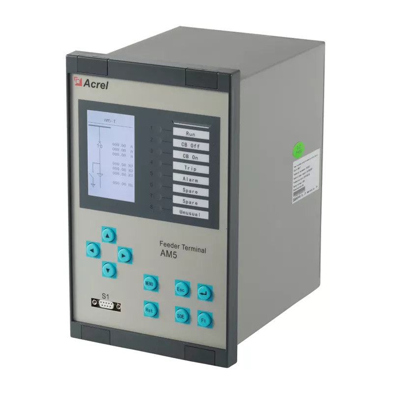
4 Selection of new comprehensive protection measurement and control equipment
The new integrated protection measurement and control device should integrate the control, protection, fault wave recording, measurement, signal alarm, switching volume acquisition and communication functions. With the three-stage nondirectional current protection as the core, it is equipped with the monitoring and collection function of line parameters, and the measurement data and protection information can be uploaded to the power monitoring system through the communication port to facilitate the automation of the distribution network. According to the public bidding results of the national suppliers for the 10kV plant power protection device transformation project of the hydropower station, the AM5SE series measurement and control device produced by Acrel Co., Ltd. was finally selected. According to the different load properties of the 10kV plant power bus, AM5SE-F line protection measurement and control device, AM5SE-T transformer protection monitoring and control device, AM5SE-M motor protection measurement and control device, AM5SE-B self-control protection measurement and control device, PT cabinet AM5SE-UB PT monitoring device, protection functions of each model are shown in the following table:
|
model |
protection function |
|
AM5SE-F Line protection measurement & control device |
Three-stage over current protection (can be closed by low pressure, can be protected in direction), reverse time limit over current protection (can be protected by low pressure closed W, two-stage zero order 101 over current / reverse time limit over current protection, two-stage zero order 1. 2 Current / reverse time over current protection, reclosing, accelerated over current protection (by low voltage closure), overload alarm, overload trip, pressure loss trip, pressure loss alarm, over voltage protection, zero order over voltage protection, reverse power protection, low frequency load reduction / high frequency protection (by slip difference), PT break alarm, control circuit break alarm, FC loop with over current lock function, non-power protection, CT break alarm, and check |
|
AM5SE-T Power distribution protection measurement and control device |
Three-stage over current protection (can be completed by composite voltage closure), reverse time limit over current protection (can be completed by composite voltage lock), two-stage zero order 101 over current protection, two-stage zero order 102 over current protection, zero order reverse time limit over current protection, overload alarm, overload trip, PT break alarm, control circuit break alarm, non-power protection, CT break alarm, FC loop with over current lock function |
|
AM5SE-B the self-projection protection measurement and control device |
Three section over current protection (by composite voltage locking, with direction locking), reverse time over current protection (by composite voltage locking), accelerated over current protection (by composite voltage locking), standby function (support 11 kinds of power supply system), PT break alarm, control circuit break alarm, bus charging protection, reclosing, overload coupling / alarm, two section zero order over current protection, zero sequence acceleration over current protection, check the same period |
|
AM5SE-M Motor protection measurement & control device |
Current protection (startup, running), current two stage protection, reverse time protection, two stage negative sequence protection, negative order reverse time limit protection, two stage zero order over current protection, hot overload, overload protection, overload alarm, overload trip, blocking protection, long start time, non-power protection, PT break alarm, control circuit break alarm, low voltage protection, zero order over voltage alarm, FC loop with over current lock function, voltage imbalance protection, phase sequence protection, voltage phase protection, over voltage protection |
In addition to the above protection function, each microcomputer protection measurement and control device has RS485 communication interface, realize the communication with the power monitoring system, realizes the independent operation circuit monitoring function, realize the switch status, and the switch circuit monitoring is more complete; built-in hop function, users can choose whether to invest. The newly configured microcomputer protection measurement and control device AM5SE series protection function is rich, and each menu can be freely set in Chinese or English, conducive to operation and maintenance.
5. Design of 10kV plant
The newly configured AM5SE series computer integrated protection measurement and control device and drawings are designed by Acrel Co., LTD. The schematic design of the secondary circuit must be based on the original 10kV high voltage cabinet secondary drawings. The terminal row layout is based on the drawing design, and the drawing design must meet the requirements of relevant regulations. For the drawing design with the same load nature, the terminal number and line number are highly uniform and have certain rules. The accuracy of the drawing design determines whether the construction and commissioning is smooth and the safe production after operation.
6. Power protection and transformation process of 6 10kV plant
The 10kV plant must meet the construction conditions: detailed construction plan and drawings; equipment managers shall complete the acceptance of new equipment; construction personnel to complete the safety education; and complete tools and materials. Construction is carried out in strict accordance with the scheme and drawings, to ensure the smooth completion of each link.
6.1 10kV plant power protection hardware transformation
The renovation construction of 10kV plant mainly has three links: the replacement of the terminal row in the switch cabinet, the removal of the old comprehensive protection measurement and control device, and the installation and assembly line and cable arrangement of the new comprehensive protection device.
6.1.1. Replace the terminal row
Terminal replacement needs to be replaced one by one, to replace one terminal; forbidden to replace two or more terminals at the same time to prevent misconnection, cause miswiring, replace the terminal row in a switch cabinet alone, and effectively prevent miswiring; AC power supply, DC power supply, trip circuit, signal circuit to add isolation, should be isolated to prevent the short connection between the terminals should be pressed without loosening. To replace the terminal row, to ensure that the original loop terminal and line number remain unchanged, and the next step of wiring and line check work can be carried out smoothly.
6.1.2 Demolition of the old comprehensive protection measurement and control device
According to the construction plan and drawings, remove the components to be abolished, including the old integrated protection measurement and control devices, intermediate relays in the switchgear, voltage relays, time relays and other components, and related secondary cables. When dismantling, pay attention to prevent artificial damage to components and mistakenly remove useful secondary cables. Organize and abolish the components and classify, specify local storage, to prevent the work site chaos, the construction site should meet the 6S requirements.
6.1.3 Installation and assembly line and cable arrangement of comprehensive protection measurement and control device
Due to the different sizes of new and old comprehensive protection measurement and control devices, the size of the installation window on the switch cabinet panel does not meet the size of the new comprehensive protection measurement and control device. The installation window on the switch cabinet panel must be cut and expanded to install the new comprehensive protection measurement and control device and prevent the scraping panel when cutting. The cable connected to the new device shall be a new cable, and all the unused cables shall be removed to prevent the existence of a parasitic circuit. The wiring shall be conducted in strict accordance with the design drawings to prevent leakage, misconnection and misswitching. The cable wiring of the new device should be neat, unified, reasonable wiring, convenient for inspection and maintenance.
6.2 Power protection and commissioning of 10 k V plant
Protection and debugging are mainly divided into four links: secondary loop line check, loop function verification, static debugging of the protection device and transmission test. Carefully check each terminal and each line number according to the construction drawings. Focus on checking the CT secondary circuit without open circuit, PT secondary circuit, polarity and wiring should be correct; check the telemetry, remote communication, remote control wiring should be correct; check the DC control circuit without short circuit, no short circuit between ground circuit LN; measure the DC control circuit insulation resistance meets the requirements (1000V); measure whether the AC / DC circuit with electricity. It is worth noting that, because the outsourcing unit is not familiar with the secondary circuit of the factory, it is easy to miss and misconnect in the transformation process.
The AC voltage and DC control loops are powered on to verify the functions of each loop. Check that the telemetry, remote signaling, and remote control signals are correct, the meters, indicator lights, lighting, and heater circuits are normal; the anti-jump function of the switch body is correct. Power on the control loop to further verify that the wiring of each loop is correct.
The static debugging of the protection device is to carry out the sampling inspection of the device, the uploading and checking of the fixed value, and the function inspection of the device. Check the line protection device AM5SE-F, transformer protection device AM5SE-T, motor protection device AM5SE-M, standby self-switching device AM5SE-B, and PT monitoring by means of applying current on the CT secondary side and applying voltage analog to the PT cabinet terminal. The device AM5SE-UB, voltmeter, ammeter, and monitoring system are displayed correctly, and the phase sequence and phase of the AC voltage and AC current loop are verified to be correct. Set the fixed value according to the fixed value single-pair protection device and check it to ensure that the fixed value is correct. The protection function inspection is to verify the correctness of the action logic and action time of the AM5SE series microcomputer protection measurement and control device by adding analog quantity, there will be no rejection and malfunction, and the action time should meet the requirements. The static debugging of the protection device ensures that the protection device can respond sensitively to faults, and send out alarm signals and trip instructions reliably and quickly.
The data connection between the comprehensive protection measurement and control device and the power monitoring system is correct, and the operation status, setting value, event record and other information on the protection device can be collected in real time in the background. The protection device is connected to the background, which improves the management of the relay protection system and the automation level of fault information processing.
The transmission test is to simulate the amount of fault collected by the protection device, and the protection device should exit the trip switch to verify the correctness of the device protection logic, trip circuit and signal circuit; and to verify that the switch can be properly opened and closed remotely through the operation of the host computer. A complete transmission test should be done for each set of protection devices to ensure that the protection logic of each switch cabinet protection device, the protection outlet tripping, the remote opening and closing switch, and the correct signal indication.
6.3 Problems encountered in the transformation and optimization
After the transformation of the new comprehensive protection measurement and control device was completed, during the transmission test, it was found that the switch could only be closed once. If it was closed again, it could only be closed after restarting the control power supply. Through analysis, it is found that there is no normally closed point in the closing coil of the circuit breaker. Since the closing relay is set in the protection device to ensure that the circuit breaker can be closed reliably, at this time, since there is no normally closed point in the closing coil of the circuit breaker, after closing If there is no breakpoint, the energy of the closing and holding relay cannot be released, so it needs to be restarted and the closing and holding relay can be released before the next closing. After many times of communication with the circuit breaker manufacturer and the relevant personnel of the hydropower station, a set of normally closed points are connected in series before the closing coil, thus solving the above problems. Taking the AM5SE-T transformer protection measurement and control device as an example, the secondary diagram of the opening and closing circuit of the hydropower station reconstruction is shown in Figure 2.

Figure 2 quadratic diagram of AM5SE-T split circuit
7 Transformation of the 10kV electric power monitoring system
In order to monitor the operation and data collection of the whole distribution room in real time, a set of Acrel-2000Z power monitoring system is configured for the hydropower station to upload the microcomputer protection data to the power monitoring system to realize the power monitoring and management of 10kV substation and improve the level of automatic management. Its main functions can be realized are as follows: real-time monitoring, electric parameter query, operation report, real-time alarm, historical event query, power statistics report, user rights management, network topology, power quality monitoring, remote control function, communication management, fault recording wave, accident recall, curve query, Web access, APP access.
8. Conclusion
The transformation of the 10kV power protection device in the hydropower station has solved the problems such as serious aging of electronic components, low automation level, unfriendly man-machine interface and software, and difficult maintenance work. The replacement of AM5SE series microcomputer protection measurement and control device is more functional and humanized, Device liquid crystal more intuitive display voltage, current sampling amount and various event records; Debug software function is powerful, easy to operate, easy to master, friendly software interface; The operation circuit has the function of monitoring switch switch and control circuit disconnection; The device panel indicator light directly shows the switch jump position and close status, For the operation and maintenance personnel is more intuitive; The configured AM5SE-M motor protection measurement and control device adds the motor starting / running state recognition, And equipped with the starting section, running the section, running the two section and other protection functions, Solve the motor starting current is large, Easy to cause a false jump problem; The protection device is equipped with an RS485 communication interface, The communication interface is connected between the protection devices by "hand in hand", Data is delivered to the Acrel-2000Z Power Monitoring System, Convenient to view the protection information and fault information management. Since the transformation of the new comprehensive protection measurement and control device has been put into operation, the equipment has been in normal operation. The application of the new comprehensive protection device has rich protection functions, friendly operation interface and convenient operation and maintenance, which improves the reliable operation of the hydropower station plant and ensures the safety and stable production of the plant, which is of obvious significance.
Reference
[1] Nb / T 35010-2013 code for design of relay protection of hydropower plants
[2] DL / T 5164-2002 technical code for design of auxiliary power of power plant
[3] GB / T 50171-2012 code for construction and acceptance of panel, cabinet and secondary circuit wiring of electrical equipment installation engineering
[4] Huang Jinxin. Transformation of 10kV auxiliary power protection device of Longtan Hydropower Station
[5] Integrated automation and operation and maintenance solution of ankrui user substation. November 2021
Post time: Aug-17-2022