Elevator Regenerative Energy Metering and Monitoring Solution
A practical architecture for measuring recovered elevator energy, verifying conversion efficiency and monitoring power quality across single buildings or multi-site portfolios.
Elevators are potential-energy loads. During normal operation, the traction motor does not always consume electricity; under certain conditions it is driven mechanically and operates as a generator. This occurs most commonly when a heavily loaded car travels down, a lightly loaded or empty car travels up, or the elevator decelerates before reaching a floor.
In a conventional drive system, this regenerative energy raises the voltage of the variable-frequency drive’s DC bus. A braking resistor then converts the surplus energy into heat. In addition to wasting recoverable energy, this heat increases the cooling burden in the machine room.
How an Elevator Energy Feedback System Works
An elevator energy feedback unit captures the regenerative energy from the drive’s DC link, converts it into grid-synchronised AC power and returns it to the building’s low-voltage distribution network. The operating sequence can be summarised as follows:
The inverter output must match the connected network in voltage, frequency and phase. Filtering and protection functions are also required to control harmonics and ensure safe operation. Because actual performance depends on elevator duty cycle, loading profile, drive configuration and recovery-device settings, project savings should be verified using measured data rather than a fixed percentage assumption.
Why Metering Is Essential
A feedback device can indicate that it is operating, but this alone does not show how much energy is recovered, whether the conversion efficiency meets the project target, or whether the returned current remains within the required power-quality limits. A complete measurement plan should answer four questions:
- How much energy does the elevator import from the building network?
- How much regenerative energy is exported back to the network?
- What is the conversion efficiency between the DC input and AC output of the feedback unit?
- Are power factor, current harmonics and operating conditions acceptable?
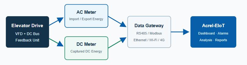
For performance verification, high-accuracy bidirectional meters can be installed on both sides of the feedback device. The DC-side meter measures captured regenerative energy, while the AC-side meter measures the useful energy returned to the building. Time-synchronised readings provide the basis for calculating conversion efficiency:
Conversion efficiency (%) = AC energy returned ÷ DC regenerative energy captured × 100
Recommended Measurement Architecture
Building Supply or Feedback Connection Point
Install a three-phase bidirectional meter at the elevator distribution incomer or the regenerative unit’s grid connection point. This records imported active energy, exported active energy, voltage, current, power, power factor and other operating values.
Recommended: DTSD1352 for RS485-based wired systems, or ADW300 for retrofit projects requiring split-core CTs and optional wireless communication.
Regenerative Unit Input
Where device-level conversion efficiency or a DC storage system must be evaluated, install a DJSF1352-RN DC energy meter with a compatible shunt or Hall-effect current sensor on the DC side.
Typical measurements: DC voltage, DC current, power, forward/reverse energy and charging/discharging energy.
Meter and Communication Selection
| Device | Role in the Solution | Best-Fit Scenario |
|---|---|---|
| DTSD1352 Three-phase Bidirectional DIN-rail energy meter |
Bidirectional active-energy measurement, electrical parameters and RS485/Modbus communication. Accuracy and detailed functions depend on the selected variant. | New installations and multi-elevator projects with wired data acquisition. |
| ADW300 Wireless IoT energy meter |
Three-phase measurement with split-core CT options and communication configurations such as RS485, Wi-Fi or 4G. | Existing buildings where shutdown time or new communication cabling should be minimised. |
| DJSF1352-RN DC energy meter |
Measures DC voltage, current, power and forward/reverse energy; supports compatible shunt or Hall-sensor inputs according to configuration. | DC-bus energy measurement, efficiency verification and elevator storage applications. |
| AHKC series Hall-effect current sensor |
Provides an isolated current signal to the DC meter. The range and output must be selected for the actual DC circuit. | Non-intrusive or isolated DC-current sensing. |
| ANet / AWT100 Gateway or communication terminal |
Collects meter data through RS485/Modbus and forwards it through Ethernet, Wi-Fi or 4G, depending on model. | Connection to Acrel-EIoT or a compatible third-party platform. |
| Acrel-EIoT Energy IoT platform |
Provides dashboards, trend analysis, alarms, reports, device records and multi-terminal access. | Central monitoring for individual buildings or distributed elevator portfolios. |
Data Available to Building Operators
Once the meters are connected to the monitoring platform, facility teams can review:
- Grid energy imported by each elevator or elevator group;
- Regenerative energy exported to the building network;
- Daily, monthly and annual recovery trends;
- Net energy consumption and verified recovery ratio;
- DC-to-AC conversion efficiency where both sides are metered;
- Voltage, current, power factor and selected power-quality indicators;
- Communication loss, abnormal readings and configurable alarms;
- Energy reports for sustainability, retrofit evaluation and maintenance review.
Suitable Applications in Singapore
This solution is particularly relevant to high-rise residential developments, office towers, hotels, hospitals, shopping centres, transport facilities and mixed-use buildings with frequent elevator operation. It can support both new construction and retrofit projects, with wired communication for structured installations and wireless options for sites where cabling is difficult.
For an existing building, a practical approach is to start with a pilot elevator or one elevator bank. The pilot establishes a measured baseline, confirms communication performance and validates the expected recovery before the design is expanded across the property.
Project Implementation Steps
- Site survey: confirm the elevator drive, regenerative unit, distribution system, DC-bus voltage, current range and available installation space.
- Define the measurement boundary: decide whether the project needs building-level net-energy monitoring, feedback-unit efficiency verification, or both.
- Select meters and sensors: match AC CT ratios, DC sensor ranges, accuracy requirements and communication interfaces.
- Plan data connectivity: choose RS485/Ethernet for wired projects or Wi-Fi/4G where site conditions require wireless access.
- Commission and validate: verify import/export direction, meter scaling, time synchronisation and platform data under representative elevator operating conditions.
- Analyse and report: compare measured recovery against the baseline and track long-term performance.
Plan Your Elevator Energy Monitoring Project
Acrel can support meter selection, sensor matching, communication architecture and platform integration for elevator regenerative-energy projects. To prepare a proposal, provide the elevator supply voltage, rated current or power, DC-bus voltage, number of elevators, communication preference and the required measurement objective.
Product functions and specifications vary by model and configuration. Final selection must be confirmed against the latest datasheets, project drawings and local installation requirements.
Post time: Jul-16-2026