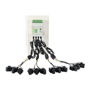
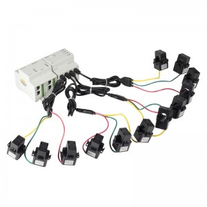
AMC16Z-FAK48 Mehrkanal-Wechselstrom-Leistungsmesser für DIN-Schienenmontage
Der Mehrkanal-Wechselstromzähler der Serie AMC16Z für DIN-Schienenmontage wurde speziell für die zunehmend hohen Anforderungen an die Präzision des Stromverteilungsmanagements in Rechenzentren entwickelt. Er eignet sich für die zuverlässige Überwachung verschiedener Verteilergeräte.

* 24 Kanäle pro Schaltkreis von A+B
*2 unabhängige Stromkreise, der ausgehende Strom,
Wirkleistung, Wirkleistung, Blindleistung
*Installation:
DIN-Schiene 35 mm
* Abmessungen (L*B*H):
180 x 94,3 x 75 mm
Präzise Stromverteilungsüberwachung für Rechenzentren


| Terminaldefinition | Anweisung | Bemerkung |
| V+ | Hilfsstromversorgung | Stromversorgung über AMC16Z-ZA oder Betrieb mit DC12-24V |
| V- | ||
| A | RS485-Kommunikation | Anschluss an Touchscreen oder RS485-Hub |
| B | ||
| A1 | A-Kanal-Strom A-Phase positiver Pol(1) | Der erste Teil von A - Kanal ausgehende Leitung - dreiphasiger Stromeingang |
| A2 | A-Kanal-Strom B-Phase positiver Pol(1) | |
| A3 | A-Kanal-Strom C-Phase positiver Pol(1) | |
| GA1 | A-Kanal-Strom negativer gemeinsamer Anschluss(1) | |
| A4 | A-Kanal-Strom A-Phase positiver Pol(2) | Der zweite Teil von A - Kanal ausgehende Leitung - dreiphasiger Stromeingang |
| A5 | A-Kanal-Strom B-Phase positiver Pol(2) | |
| A6 | A-Kanal-Strom C-Phase positiver Pol(2) | |
| GA2 | A-Kanal-Strom negativer gemeinsamer Anschluss (2) | |
| A7 | A-Kanal-Strom A-Phase positiver Pol(3) | Der dritte Teil von A - Kanal ausgehende Leitung - dreiphasiger Stromeingang |
| A8 | A-Kanal-Strom B-Phase positiver Pol(3) | |
| A9 | A-Kanal-Strom C-Phase positiver Pol(3) | |
| GA3 | A-Kanal-Strom negativer gemeinsamer Anschluss (3) | |
| A10 | A-Kanal-Strom A-Phase positiver Pol(4) | Der vierte Teil von A - Kanal ausgehende Leitung - dreiphasiger Stromeingang |
| A11 | A-Kanal-Strom B-Phase positiver Pol(4) | |
| A12 | A-Kanal-Strom C-Phase positiver Pol(4) | |
| GA4 | A-Kanal-Strom negativer gemeinsamer Anschluss (4) | |
| A13 | A-Kanal-Strom A-Phase positiver Pol(5) | Der fünfte Teil von A - Kanal ausgehende Leitung - dreiphasiger Stromeingang |
| A14 | A-Kanal-Strom B-Phase positiver Pol(5) | |
| A15 | A-Kanal-Strom C-Phase positiver Pol(5) | |
| GA5 | A-Kanal-Strom negativer gemeinsamer Anschluss (5) | |
| A16 | A-Kanal-Strom A-Phase positiver Pol(6) | Der sechste Teil von A - Kanal ausgehende Leitung - dreiphasiger Stromeingang |
| A17 | A-Kanal-Strom B-Phase positiver Pol(6) | |
| A18 | A-Kanal-Strom C-Phase positiver Pol(6) | |
| GA6 | A-Kanal-Strom negativer gemeinsamer Anschluss (6) | |
| A19 | A-Kanal-Strom A-Phase positiver Pol(7) | Der siebte Teil von A - Kanal abgehende Leitung - dreiphasiger Stromeingang |
| A20 | A-Kanal-Strom B-Phase positiver Pol(7) | |
| A21 | A-Kanal-Strom C-Phase positiver Pol(7) | |
| GA7 | A-Kanal-Strom negativer gemeinsamer Anschluss (7) | |
| A22 | A-Kanal-Strom A-Phase positiver Pol(8) | Der achte Teil von A - Kanal ausgehende Leitung - dreiphasiger Stromeingang |
| A23 | A-Kanal-Strom B-Phase positiver Pol(8) | |
| A24 | A-Kanal-Strom C-Phase positiver Pol(8) | |
| GA8 | A-Kanal-Strom negativer gemeinsamer Anschluss (8) | |
| B1 | B-Kanal-Strom A-Phase positiver Pol(1) | Die erste Gruppe B - Kanal ausgehende Leitung - dreiphasiger Stromeingang |
| B2 | B-Kanal-Strom B-Phase positiver Pol(1) | |
| B3 | B-Kanal-Strom C-Phase positiver Pol(1) | |
| GB1 | B-Kanal-Strom negativer gemeinsamer Anschluss(1) | |
| B4 | B-Kanal-Strom A-Phase positiver Pol(2) | Die zweite Gruppe B - Kanal ausgehende Leitung - dreiphasiger Stromeingang |
| B5 | B-Kanal-Strom B-Phase positiver Pol(2) | |
| B6 | B-Kanal-Strom C-Phase positiver Pol(2) | |
| GB2 | B-Kanal-Strom negativer gemeinsamer Anschluss(2) | |
| B7 | B-Kanal-Strom A-Phase positiver Pol(3) | Die dritte Gruppe B - Kanal ausgehende Leitung - dreiphasiger Stromeingang |
| B8 | B-Kanal-Strom B-Phase positiver Pol(3) | |
| B9 | B-Kanal-Strom C-Phase positiver Pol(3) | |
| GB3 | B-Kanal-Strom negativer gemeinsamer Anschluss (3) | |
| B10 | B-Kanal-Strom A-Phase positiver Pol(4) | Die vierte Gruppe B - Kanal ausgehende Leitung - dreiphasiger Stromeingang |
| B11 | B-Kanal-Strom B-Phase positiver Pol(4) | |
| B12 | B-Kanal-Strom C-Phase positiver Pol(4) | |
| GB4 | B-Kanal-Strom negativer gemeinsamer Anschluss (4) | |
| B13 | B-Kanal-Strom A-Phase positiver Pol(5) | Fünfte Gruppe B - Kanal, ausgehende Leitung, dreiphasiger Stromeingang |
| B14 | B-Kanal-Strom B-Phase positiver Pol(5) | |
| B15 | B-Kanal-Strom C-Phase positiver Pol(5) | |
| GB5 | B-Kanal-Strom negativer gemeinsamer Anschluss (5) | |
| B16 | B-Kanal-Strom A-Phase positiver Pol(6) | Sechste Gruppe B - Kanal, ausgehende Leitung, dreiphasiger Stromeingang |
| B17 | B-Kanal-Strom B-Phase positiver Pol(6) | |
| B18 | B-Kanal-Strom C-Phase positiver Pol(6) | |
| GB6 | B-Kanal-Strom negativer gemeinsamer Anschluss (6) | |
| B19 | B-Kanal-Strom A-Phase positiver Pol(7) | Siebter Gruppe B - Kanal, ausgehende Leitung, dreiphasiger Stromeingang |
| B20 | B-Kanal-Strom B-Phase positiver Pol(7) | |
| B21 | B-Kanal-Strom C-Phase positiver Pol(7) | |
| GB7 | B-Kanal-Strom negativer gemeinsamer Anschluss (7) | |
| B22 | B-Kanal-Strom A-Phase positiver Pol(8) | Achte Gruppe B - Kanal ausgehende Leitung dreiphasiger Stromeingang |
| B23 | B-Kanal-Strom B-Phase positiver Pol(8) | |
| B24 | B-Kanal-Strom C-Phase positiver Pol(8) | |
| GB8 | B-Kanal-Strom negativer gemeinsamer Anschluss (8) | |
| KA1 | Wechselspannung A-Kanal A-Phase (1) | Der erste Teil von A - Kanal DI |
| KA2 | Wechselspannung A-Kanal B-Phase (1) | |
| KA3 | Wechselspannung A-Kanal C Phase (1) | |
| KA4 | Wechselspannung A-Kanal A-Phase (2) | |
| KA5 | Wechselspannung A-Kanal B-Phase (2) | |
| KA6 | A-Kanal-Wechselspannung C-Phase (2) | |
| KA7 | Wechselspannung A-Kanal A-Phase (3) | |
| KA8 | Wechselspannung A-Kanal B-Phase (3) | |
| KA9 | A-Kanal-Wechselspannung C-Phase (3) | |
| KA10 | Wechselspannung A-Kanal A-Phase (4) | |
| KA11 | Wechselspannung A-Kanal B-Phase (4) | |
| KA12 | A-Kanal-Wechselspannung C-Phase (4) | |
| UNA | A-Kanal-Wechselspannungsnullleitung | |
| KA13 | Wechselspannung A-Kanal A-Phase (5) | Der zweite Teil von A - Kanal DI |
| KA14 | Wechselspannung A-Kanal B-Phase (5) | |
| KA15 | A-Kanal-Wechselspannung C-Phase (5) | |
| KA16 | Wechselspannung A-Kanal A-Phase (6) | |
| KA17 | Wechselspannung A-Kanal B-Phase (6) | |
| KA18 | A-Kanal-Wechselspannung C-Phase (6) | |
| KA19 | Wechselspannung A-Kanal A-Phase (7) | |
| KA20 | Wechselspannung A-Kanal B-Phase (7) | |
| KA21 | A-Kanal-Wechselspannung C-Phase (7) | |
| KA22 | Wechselspannung A-Kanal A-Phase (8) | |
| KA23 | A-Kanal-Wechselspannung Phase B (8) | |
| KA24 | A-Kanal-Wechselspannung C-Phase (8) | |
| KB1 | Wechselspannung B-Kanal A Phase (1) | Der erste Gruppe-B-Kanal DI |
| KB2 | Wechselspannung B-Kanal B-Phase (1) | |
| KB3 | Wechselspannung B-Kanal C Phase (1) | |
| KB4 | Wechselspannung B-Kanal A Phase (2) | |
| KB5 | Wechselspannung B-Kanal B-Phase (2) | |
| KB6 | Wechselspannung B-Kanal C Phase (2) | |
| KB7 | Wechselspannung B-Kanal A Phase (3) | |
| KB8 | Wechselspannung B-Kanal B-Phase (3) | |
| KB9 | Wechselspannung B-Kanal C Phase (3) | |
| KB10 | Wechselspannung B-Kanal A Phase (4) | |
| KB11 | Wechselspannung B-Kanal B-Phase (4) | |
| KB12 | Wechselspannung B-Kanal C-Phase (4) | |
| UNB | B-Kanal-Wechselspannungsnullleitung | |
| KB13 | Wechselspannung B-Kanal A Phase (5) |
Der zweite B-Kanal DI |
| KB14 | Wechselspannung B-Kanal B-Phase (5) | |
| KB15 | Wechselspannung B-Kanal C-Phase (5) | |
| KB16 | Wechselspannung B-Kanal A Phase (6) | |
| KB17 | Wechselspannung B-Kanal B-Phase (6) | |
| KB18 | Wechselspannung B-Kanal C-Phase (6) | |
| KB19 | Wechselspannung B-Kanal A Phase (7) | |
| KB20 | Wechselspannung B-Kanal B-Phase (7) | |
| KB21 | Wechselspannung B-Kanal C-Phase (7) | |
| KB22 | Wechselspannung B-Kanal A Phase (8) | |
| KB23 | Wechselspannung B-Kanal B-Phase (8) | |
| KB24 | Wechselspannung B-Kanal C-Phase (8) |
1,1 TDie Messung des Geräts ist nicht genau
*Prüfen Sie, ob die Verdrahtung für Spannung und Strom korrekt ist und ob die Eingangs- und Ausgangsleitungen des Stromeingangs korrekt sind;
*Prüfen Sie, ob die CT-Einstellung des Geräts der tatsächlich extern verwendeten CT entspricht;
1.2Spannung und Stromstärke werden korrekt gemessen, die Leistung jedoch nicht genau.
*Prüfen Sie, ob die aktuelle Eingangsrichtung korrekt ist;
*Prüfen Sie, ob die jeweilige Phase jeder Stromschleife korrekt ist;Der Ausgangsstromkreis muss entsprechend dem tatsächlichen Anschluss angepasst werden.
1.3Abnormal Kommunikation
*Prüfen Sie, ob das Kommunikationskabel ordnungsgemäß angeschlossen ist;
*Prüfen Sie, ob die A- und B-Anschlüsse der Kommunikation verschachtelt sind;
*Prüfen Sie, ob die Adresse des Geräts und die Baudrate der Kommunikation korrekt eingestellt sind;
*Wenn die Kommunikation mehrerer Geräte gestört ist, prüfen Sie zunächst, ob die Kommunikation mit einem einzelnen Gerät normal funktioniert.
1.4Es fließen Spannung, Strom und Leistung an, aber Elektrizität hat keinen Wert.
*Überprüfen Sie die Einstellung des Stromwandlerverhältnisses der Eingangsleitung.
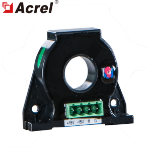
1,5Der Strom des AMC16Z-ZD hat einen Wert, wenn keine Last anliegt.
*Passen Sie den Nullpunkt des AMC16Z-ZD-Stroms an. (Der Nullpunkt des DC-Hall-Sensors ist nicht konsistent, die Abweichung ist groß und muss angepasst werden.)
Haben Sie noch Fragen? Bitte kontaktieren Sie uns, wir melden uns schnellstmöglich bei Ihnen.
| MINDESTVERPACKUNG
| Verpackungsabmessungen (1 Stück) 220 x 170 x 90 mm | Paketgewicht (1 Stück) 0,28 kg | ||
| GESAMTE BOXVERPACKUNG | Verpackungsabmessungen (24 Stück) 615 x 480 x 395 mm | Paketgewicht (24 Stück) 6,72 kg | ||
| PRODUKT-HS-CODE
| 9028309000 | |||
-
4G Remote Wireless Smart Gateway
-
ADW210 Serie Mehrschleifen-Leistungsmesser
-
Mehrkanal-Energiezähler der Serie ADW200
-
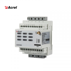
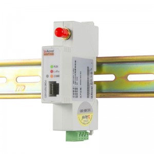
ADW350WD Mehrkreis-Gleichstrom-Energiezähler
-
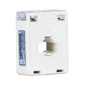
Stromwandler der Serie AKH-0.66/I
-
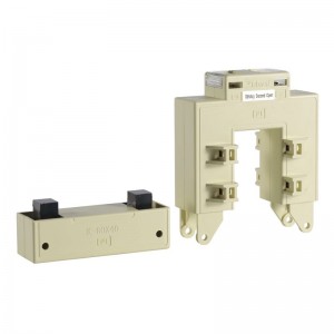
AKH-0.66/K Serie geteilter Kernstromwandler
-
AWT100 drahtloses Kommunikationsterminal
-
AHLC-LTA Gleichstrom-Leckstromsensor